Designing an FIR filter on FPGA still starts with fundamentals: convolution, z-domain structure, fixed-point limits, and synthesis constraints. AI can accelerate the workflow, but it does not remove the need for engineering judgment. In practice, the speed gains only hold when the output is verified with the same rigor used in a manual flow.
This post walks through both paths using the same 8-tap low-pass example:
- Manual path: derive and validate the math, implement C reference code, write synthesizable Verilog, and verify behavior.
- AI-assisted path: use an agent to generate and iterate quickly, then validate outputs against deterministic checks.
Companion document
For the full engineering reference (extended derivations, full C and Verilog listings, and workflow comparison tables), download the companion PDF:
The baseline: what must be correct before writing RTL
For a causal FIR of length \(N\):
\[ y[n] = \sum_{k=0}^{N-1} h[k]\,x[n-k] \]and
\[ H(z) = \sum_{k=0}^{N-1} h[k] z^{-k} \]If you rewrite \(H(z)\) as \(P(z)/z^{N-1}\), the denominator gives \(N-1\) poles at \(z=0\). That part is structural. The design behavior is driven by the zeros of \(P(z)\).
For the coefficient set used here (Q15):
\[ h = [1024, 2048, 4096, 8192, 8192, 4096, 2048, 1024] \]Key properties:
- Symmetric taps \(h[k]=h[N-1-k]\) give linear phase.
- Group delay is constant: \((N-1)/2 = 3.5\) samples.
- DC gain is \(\sum h / 32768 = 31744/32768 \approx 0.969\).
- Nyquist response is zero for this set, confirming low-pass behavior.
These are fast checks and they catch many implementation mistakes early.
Pole-zero analysis: manual C vs generated code
For \(N=8\), the numerator polynomial is degree 7, so closed-form roots are not practical. A numerical root finder (for example, Durand-Kerner) is the right engineering move.
In a manual flow, writing and debugging the complex arithmetic takes time but gives full control over convergence and diagnostics. In an AI-assisted flow, the same solver is typically generated in seconds.
The trade-off is straightforward:
- Manual: slower, but you understand every line and failure mode.
- AI-assisted: much faster draft, but you must verify normalization, convergence tolerance, and root interpretation.
For symmetric palindromic FIR polynomials, zeros appear in reciprocal-conjugate pairs. In this coefficient set, zeros lie on the unit circle, which matches stopband notch behavior.
RTL architecture choice: direct form or transpose form
Both forms are valid. The right choice depends on clock target and debug priorities.
Direct form is often easier to inspect in simulation because the delay line is explicit. Transpose form usually closes timing at higher frequencies on modern FPGA DSP slices due to cascade-friendly accumulation.
For Xilinx UltraScale+ devices, transpose form maps naturally to DSP48E2 cascade paths (PCIN/PCOUT), reducing fabric routing pressure in the accumulator chain.
Practical rule:
- If you are iterating quickly or tap count is modest, direct form is easier to debug.
- If Fmax is tight, transpose form is usually the safer production architecture.
Fixed-point discipline is not optional
A reliable accumulator width rule is:
\[ ACC\_WIDTH \ge DATA\_WIDTH + COEF\_WIDTH + \lceil \log_2(N) \rceil \]For 16-bit data, 16-bit coefficients, and \(N=8\):
\[ ACC\_WIDTH \ge 16 + 16 + 3 = 35 \]Using 40 bits gives practical margin and simplifies edge-case handling when pre-adders and saturation logic are included.
Before touching synthesis reports, validate three items in software:
- Impulse response reproduces coefficients in order.
- DC and Nyquist points match expected values.
- Overflow behavior is explicit and deterministic.
This avoids burning time in RTL debug for issues that are purely numeric.
What AI changes in the engineering loop
AI is strong at producing boilerplate and first-pass implementations:
- C99 FIR helpers (frequency response, coefficient generation, fixed-point simulation)
- Parameterized Verilog modules and testbenches
- Documentation and consistency checks across artifacts
AI is weaker where project context and hardware constraints dominate:
- Timing closure decisions
- Device-specific synthesis behavior
- Numerical edge cases at format boundaries
- Silent assumptions in prompt wording
The practical operating model is:
- Use AI for acceleration.
- Keep deterministic verification as gate criteria.
- Treat generated code as untrusted until it passes the same checks as handwritten code.
That model preserves velocity without lowering engineering standards.
A verification protocol that scales
When using an agent for DSP + FPGA tasks, this checklist keeps quality stable:
- Confirm poles and zero magnitudes against expected structure.
- Recompute key response points independently (at least DC and Nyquist).
- Run impulse and sine tests in simulation and compare with software reference output.
- Inspect synthesis utilization to confirm intended DSP inference.
- Check timing reports for the actual critical path, not the expected one.
If these checks pass, AI is a clear multiplier. If they are skipped, speed gains disappear quickly.
Closing perspective
Manual engineering and AI-assisted engineering are not competing methods. They are layered methods. The manual path builds the model in your head; the AI path compresses execution time once that model exists.
In FIR-on-FPGA work, that distinction matters. The engineer still owns correctness, timing, and numerical integrity. AI can do a lot of work. It cannot assume responsibility.
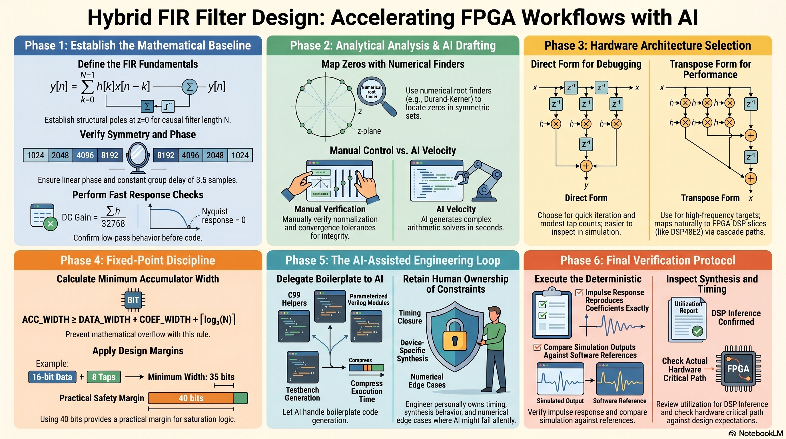
This diagram summarizes the full thread of the post: start from FIR fundamentals in the z-domain, choose an RTL structure that fits timing targets, validate fixed-point behavior before synthesis, and use AI as an accelerator only after deterministic checks are in place. It is the same workflow, with and without AI; the difference is execution speed, not verification rigor.
References
- A. V. Oppenheim and R. W. Schafer, Discrete-Time Signal Processing, 3rd ed., Pearson, 2010.
- J. G. Proakis and D. G. Manolakis, Digital Signal Processing: Principles, Algorithms, and Applications, 4th ed., Pearson, 2006.
- Xilinx, FIR Compiler v7.2 Product Guide (PG149), AMD/Xilinx.
- Xilinx, UltraScale Architecture DSP Slice User Guide (UG579), AMD/Xilinx.
- Intel, AN 306: Implementing FIR Filters in Intel FPGA Devices, Intel Corporation.
- IEEE, IEEE Std 1800-2017: SystemVerilog Language Reference Manual, IEEE.